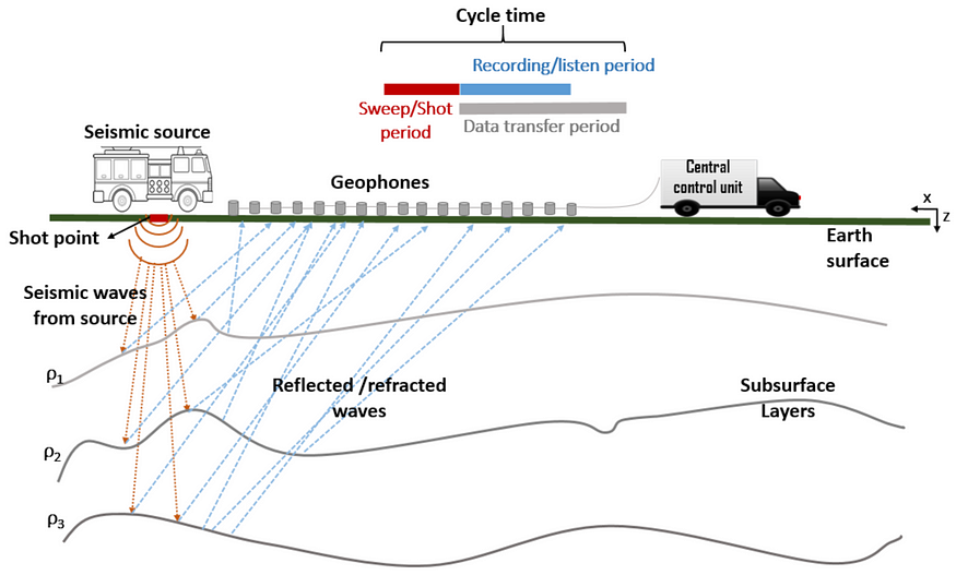
A geophone is a device that converts ground motion into electrical signals, which can be used to monitor seismic activity. A seismic monitoring system is a network of geophones that collect and analyze data from different locations. In this project, we will use an Arduino-based microcontroller to interface with a geophone sensor and transmit the data wirelessly to a computer. We will also use a software tool called SeisGram2K to visualize and process the seismic signals.
The main components of this project are:
— A geophone sensor: This is a coil of wire attached to a mass inside a metal case. When the ground moves, the mass moves relative to the coil, inducing a voltage that is proportional to the ground velocity. We will use a 4.5 Hz geophone, which is sensitive to low-frequency vibrations.
— An Arduino Uno board: This is a microcontroller that can read analogue and digital signals, perform calculations, and communicate with other devices. We will use it to read the voltage from the geophone and convert it into digital values.
— A wireless module: This is a device that can send and receive data wirelessly using radio waves. We will use an XBee module, which is compatible with the Arduino and can communicate over long distances.
— A computer: This is where we will receive and display the data from the Arduino. We will use a software tool called SeisGram2K, which is a Java application that can plot and analyze seismic signals in real time.

The steps to build this project are:
— Connect the geophone sensor to the Arduino board using jumper wires. The positive terminal of the geophone should go to the analog pin A0, and the negative terminal should go to the ground pin.
— Connect the XBee module to the Arduino board using a shield or a breakout board. The shield or breakout board should have pins that match the Arduino pins. The TX pin of the XBee should go to the RX pin of the Arduino, and vice versa. The VCC pin of the XBee should go to the 5V pin of the Arduino, and the GND pin should go to the ground pin.
— Connect another XBee module to the computer using a USB adapter or a serial port. The USB adapter or serial port should have pins that match the XBee pins. The TX pin of the XBee should go to the RX pin of the adapter or port, and vice versa. The VCC pin of the XBee should go to the 5V pin of the adapter or port, and the GND pin should go to the ground pin.
— Download and install the Arduino IDE software on your computer. This is where you will write and upload code to your Arduino board.
— Download and install the SeisGram2K software on your computer. This is where you will receive and display data from your Arduino board.
— Write and upload code to your Arduino board using the Arduino IDE. The code should read analog values from the geophone sensor, map them to a range of 0 to 1023, and send them wirelessly using the XBee module.
— Configure your XBee modules using a software tool called X-CTU. This is where you will set up parameters such as baud rate, channel, and network ID for your wireless communication.
— Run SeisGram2K on your computer and select the serial port that corresponds to your XBee module. You should see a graph that shows the seismic signals from your geophone sensor in real time.
You have successfully created an Arduino-based project for a geophone and seismic monitoring system. You can now experiment with different settings, locations, and sources of vibrations to observe how they affect your seismic signals.

XBee is a brand of radio communication modules developed by Digi International. These modules are widely used for wireless communication in various applications such as home automation, industrial control systems, robotics, and Internet of Things (IoT) projects.
XBee modules provide a simple and reliable way to establish wireless communication between devices. They operate on various frequencies and support different protocols, including Zigbee, Wi-Fi, and Bluetooth. XBee modules come in different form factors, including through-hole and surface-mount, to suit different integration requirements.
Here are a few links where you can find more information about XBee:
1. Digi International XBee Product Page:
— Website: https://www.digi.com/products/embedded-systems/digi-xbee
— This is the official product page of XBee modules by Digi International. It provides an overview of the different XBee modules, their features, and specifications.
2. XBee Official Documentation:
— Website: https://www.digi.com/resources/documentation/digidocs/90001526/
— This is the official documentation provided by Digi International. It includes user guides, datasheets, application notes, and other technical resources related to XBee modules.
3. XBee Examples and Tutorials on GitHub:
— Website: https://github.com/digidotcom/XBeeExamples
— This GitHub repository contains various code examples and tutorials for working with XBee modules. It covers topics such as basic communication, mesh networking, sensor integration, and more.
Please note that providing specific code would require a more specific question or requirement related to XBee.

LoraWAN and XBee are both wireless communication technologies, but they differ in several aspects. Here’s a comparison between LoraWAN and XBee modules:
1. Technology
— LoraWAN: LoraWAN is a low-power wide area network (LPWAN) technology that operates in the sub-GHz frequency range. It uses the LoRa modulation technique to achieve long-range communication with low power consumption.
— XBee: XBee modules are radio communication modules that support various wireless protocols such as Zigbee, Wi-Fi, and Bluetooth. They operate in the 2.4 GHz frequency range and use different modulation techniques depending on the specific module.
2. Range
— LoraWAN: LoraWAN has a long-range capability, typically reaching several kilometers in open areas. This makes it suitable for applications that require communication over long distances.
— XBee: XBee modules have a shorter range compared to LoraWAN, typically ranging from a few hundred meters to a few kilometers, depending on the specific module and environment.
3. Power Consumption
— LoraWAN: LoraWAN is designed for low-power applications. The technology allows devices to operate on batteries for extended periods, making it suitable for IoT applications that require long battery life.
— XBee: XBee modules have varying power consumption levels depending on the specific module and the wireless protocol being used. Some XBee modules are designed for low-power applications, while others may consume more power.
4. Network Topology
— LoraWAN: LoraWAN operates in a star-of-stars network topology, where end devices communicate with gateways. The gateways then forward the data to a central network server.
— XBee: XBee modules support different network topologies depending on the specific protocol being used. Zigbee, for example, supports mesh networking, allowing devices to communicate with each other directly or through intermediate nodes.
5. Data Rate
— LoraWAN: LoraWAN has a relatively low data rate, typically ranging from a few hundred bits per second to a few kilobits per second. This makes it suitable for applications that require small amounts of data to be transmitted over long distances.
— XBee: XBee modules have varying data rates depending on the specific module and protocol being used. Some modules support higher data rates, such as Wi-Fi or Bluetooth, while others, like Zigbee, have lower data rates.
6. Ecosystem and Adoption
— LoraWAN: LoraWAN has gained significant adoption in the IoT industry and has a growing ecosystem of devices, gateways, and network providers. It is supported by the LoRa Alliance, a consortium of companies promoting the technology.
— XBee: XBee modules have been widely used in various industries for wireless communication. They have a mature ecosystem with a range of modules, development tools, and community support.
It’s important to note that the choice between LoraWAN and XBee modules depends on the specific requirements of your application, such as range, power consumption, data rate, and network topology.
=============================================
Project director: Nap Marikyan
Ideas: Konstantin Stalinsky [Internet Society — Georgia]

- Monitoring seismological activity in Samtskhe-Javakheti [Georgia], while comparing it with infrasonic waves in rocks, and showing correlations is crucial to confirm or disprove the above theory.
![Comparison of LoraWAN & XBee technology [modules], for geophone and/or seismograph data transmission Comparison of LoraWAN & XBee technology [modules], for geophone and/or seismograph data transmission](https://iot.org.ge/wp-content/uploads/people-IoT.png)

